- 您现在的位置:买卖IC网 > Sheet目录634 > PS21A79 (Powerex Inc)MOD IPM 600V 50A LARGE DIP
�� �
�
�MITSUBISHI� SEMICONDUCTOR� <� Dual-In-Line� Package� Intelligent� Power� Module>�
�PS21A79�
�TRANSFER-MOLD� TYPE�
�INSULATED� TYPE�
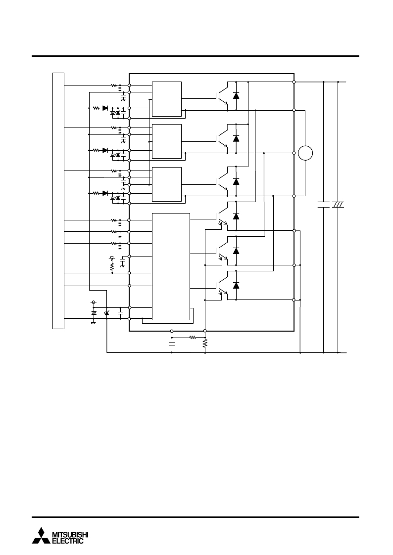
�Fig.� 7� AN� EXAMPLE� OF� APPLICATION� CIRCUIT�
�R3�
�C5�
�U� P� (1)�
�V� P1� (3)�
�IGBT1�
�Di1�
�P(40)�
�C2�
�HVIC�
�D2�
�+�
�V� UFB� (4)�
�V� UFS� (6)�
�U(39)�
�C1� D1� C2�
�R3�
�C5�
�C2�
�V� P� (7)�
�V� P1� (9)�
�HVIC�
�IGBT2�
�Di2�
�D2�
�+�
�C1� D1� C2�
�R3�
�C5�
�C2�
�V� VFB� (10)�
�V� VFS� (12)�
�W� P� (13)�
�V� P1� (14)�
�V� PC� (15)�
�HVIC�
�IGBT3�
�Di3�
�V(38)�
�M�
�D2�
�+�
�C1� D1� C2�
�V� WFB� (16)�
�V� WFS� (18)�
�IGBT4�
�Di4�
�W(37)�
�+�
�R3�
�U� N� (27)�
�C3�
�R3�
�C5�
�V� N� (28)�
�NU(36)�
�C5�
�R3�
�C5�
�W� N� (29)�
�IGBT5�
�Di5�
�5V�
�C� FO� (25)�
�NV(35)�
�R2�
�Fo(26)�
�LVIC�
�IGBT6�
�Di6�
�V� OT� (23)�
�15V�
�NW(34)�
�V� D�
�C1�
�+�
�D1�
�C2�
�V� N1� (21)�
�V� NC� (22)�
�V� NO�
�C�
�CIN(24)�
�B�
�V� SC� (19)�
�D�
�Note�
�C4�
�R1�
�Rs� Sense�
�resistor�
�A�
�N1�
�1� :If� control� GND� is� connected� to� power� GND� by� broad� pattern,� it� may� cause� malfunction� by� power� GND� fluctuation.� It� is� recommended� to� connect� control� GND�
�and� power� GND� at� only� a� point� at� which� NU,� NV,� NW� are� connected� to� power� GND� line.�
�2� :To� prevent� surge� destruction,� the� wiring� between� the� smoothing� capacitor� and� the� P,N1� terminals� should� be� as� short� as� possible.� Generally� inserting� a�
�0.1� μ� ~0.22� μ� F� snubber� capacitor� C3� between� the� P-N1� terminals� is� recommended.�
�3� :The� time� constant� R1C4� of� RC� filter� for� preventing� protection� circuit� malfunction� should� be� selected� in� the� range� of� 1.5� μ� s~2� μ� s.� SC� interrupting� time� might� vary�
�with� the� wiring� pattern.� Tight� tolerance,� temp-compensated� type� is� recommended� for� R1,C4.� When� R1� is� too� small,� it� will� leads� to� delay� of� protection.� So� R1�
�should� be� min.� 10� times� larger� resistance� than� Rs.� (Over� 100� times� is� recommended.)�
�4� :All� capacitors� should� be� mounted� as� close� to� the� terminals� of� the� DIPIPM� as� possible.� (C1:� good� temperature,� frequency� characteristic� electrolytic� type,� and�
�C2:� 0.22� μ� ~2.0� μ� F,� good� temperature,� frequency� and� DC� bias� characteristic� ceramic� type� are� recommended.)�
�5� :It� is� recommended� to� insert� a� Zener� diode� D1� (24V/1W)� between� each� pair� of� control� supply� terminals� to� prevent� surge� destruction.�
�6� :To� prevent� erroneous� SC� protection,� the� wiring� from� V� SC� terminal� to� CIN� filter� should� be� divided� at� the� point� D� that� is� close� to� the� terminal� of� sense� resistor.�
�And� the� wiring� should� be� patterned� as� short� as� possible.�
�7� :For� sense� resistor,� the� variation� within� 1%(including� temperature� characteristics),� low� inductance� type� is� recommended.� And� the� over� 1/8W� is� recommended,�
�but� it� is� necessary� to� evaluate� in� your� real� system� finally.�
�8� :To� prevent� erroneous� operation,� the� wiring� of� A,� B,� C� should� be� as� short� as� possible.�
�9� :Fo� output� is� open� drain� type.� It� should� be� pulled� up� to� the� positive� side� of� 5V� or� 15V� power� supply� with� the� resistor� that� limits� Fo� sink� current� I� Fo� under� 1mA.� In�
�the� case� pull� up� to� 5V� supply,� over� R2=5.1k� ?� is� needed.� (10k� ?� ?� is� recommended.)�
�10� :Error� signal� output� width� (t� Fo� )� can� be� set� by� the� capacitor� connected� to� C� FO� terminal.� C� FO� (typ.)� =� t� Fo� x� (9.1� x� 10� -6� )� (F)�
�11� :High� voltage� (V� RRM� =600V� or� more)� and� fast� recovery� type� (trr=less� than� 100ns� or� less)� diode� D2� should� be� used� in� the� bootstrap� circuit.�
�12� :If� high� frequency� noise� superimposed� to� the� control� supply� line,� IC� malfunction� might� happen� and� cause� erroneous� operation.� To� avoid� such� problem,� voltage�
�ripple� of� control� supply� line� should� meet� dV/dt� ≤� +/-1V/� μ� s,� Vripple� ≤� 2Vp-p.�
�13� :Input� drive� is� High-Active� type.� There� is� a� 3.3k� Ω� (min.)� pull-down� resistor� integrated� in� the� IC� input� circuit.� To� prevent� malfunction,� the� wiring� of� each� input�
�should� be� patterned� as� short� as� possible.� When� using� RC� filter� R3C5,� it� is� necessary� to� confirm� the� input� signal� level� to� meet� the� turn-on� and� turn-off� threshold�
�voltage.� Thanks� to� HVIC� inside� the� module,� direct� coupling� to� MCU� without� any� opto-coupler� or� transformer� isolation� is� possible.�
�8�
�March� 2011�
�发布紧急采购,3分钟左右您将得到回复。
相关PDF资料
PS21A7A
MOD IPM 600V 75A LARGE DIP
PS22052
MOD IPM 1200V 5A DIP
PS22053
MOD IPM 1200V 10A DIP
PS22054
MOD IPM 1200V 15A DIP
PS22056
MOD IPM 1200V 25A DIP
PS22A72
MOD IPM 1200V 5A LARGE DIP
PS22A73
MOD IPM 1200V 10A LARGE DIP
PS22A74
MOD IPM 1200V 15A LARGE DIP
相关代理商/技术参数
PS21A7A
功能描述:MOD IPM 600V 75A LARGE DIP RoHS:是 类别:半导体模块 >> 功率驱动器 系列:DIPIPM™ 标准包装:15 系列:SPM® 类型:FET 配置:三相反相器 电流:1.8A 电压:500V 电压 - 隔离:1500Vrms 封装/外壳:23-DIP 模块
PS21H-NS02HC-T00
制造商:Carlo Gavazzi 功能描述:2NC SNAP ZINC PLATED STEEL LVR
PS21H-NS02HC-Y00
制造商:Carlo Gavazzi 功能描述:
PS21H-NS02HS-T00
制造商:Carlo Gavazzi 功能描述:
PS21H-NS02HS-Y00
制造商:Carlo Gavazzi 功能描述:LSW 2NC SNAP STNLS STL SHAFT
PS21H-NS02HZ-T00
制造商:Carlo Gavazzi 功能描述:
PS21H-NS02HZ-Y00
制造商:Carlo Gavazzi 功能描述:
PS21H-NS11HC-T00
制造商:Carlo Gavazzi 功能描述:1NO+1NC SNAP ZINC PLATED STEEL LVR